
Project mẫu AVR (phần 1)1.Đèn LED nhấp nháy 1s.
- Sơ đồ mạch điện:
Sơ đồ mạch điện.
- Chương trình mẫu:
Chip type : ATmega16
Program type : Application
AVR Core Clock frequency: 8.000000 MHz
Memory model : Small
External RAM size : 0
Data Stack size : 256
************************************************** ***/
#include "mega16.h"
#include "delay.h" //khai bao thu vien ham tao tre
#define LED PORTC.0 //dinh nghi LED la PORTC.0
void main(void)
{
// Port C initialization
// Func7=In Func6=In Func5=In Func4=In Func3=In Func2=In Func1=In Func0=Out
// State7=T State6=T State5=T State4=T State3=T State2=T State1=T State0=1
PORTC=0x01; //LED duoc noi vao PORTC.0 vi vay chon trang thai led sau khi mach duoc cap nguon la LED tat
DDRC=0x01; //chon trang thai cho phep xuat ra dieu khien led
while (1)
{
LED = ~LED;//dao trang thai led ( 1-> 0 va 0-> 1)
delay_ms(500); //tre 500ms
};
}
2.8 đèn LED nhấp nháy 1s.
- Sơ đồ mạch điện:
Sơ đồ mạch điện.
- Chương trình mẫu:
Chip type : ATmega16
Program type : Application
AVR Core Clock frequency: 8.000000 MHz
Memory model : Small
External RAM size : 0
Data Stack size : 256
************************************************** ***/#include "mega16.h"
#include "delay.h" //khai bao thu vien ham tao tre
#define LED PORTC //dinh nghia LED la PORTC
void main(void)
{
// Port C initialization
// Func7=In Func6=In Func5=In Func4=In Func3=In Func2=In Func1=In Func0=Out
// State7=T State6=T State5=T State4=T State3=T State2=T State1=T State0=1
PORTC=0xFF; //LED duoc noi vao PORTC vi vay chon trang thai led sau khi mach duoc cap nguon la LED tat
DDRC=0xFF; //chon trang thai cho phep xuat ra dieu khien led while (1)
{
LED = ~LED;//dao trang thai led ( 1-> 0 va 0-> 1)
delay_ms(500); //tre 500ms
};
}3.4 LED sáng 4 LED tắt luân phiên.
- Sơ đồ mạch điện:
Sơ đồ mạch điện.
- Chương trình mẫu:
Chip type : ATmega16
Program type : Application
AVR Core Clock frequency: 8.000000 MHz
Memory model : Small
External RAM size : 0
Data Stack size : 256
************************************************** ***/
#include "mega16.h"
#include "delay.h" //khai bao thu vien ham tao tre
#define LED PORTC //dinh nghia LED la PORTC
void main(void)
{
// Port C initialization
// Func7=In Func6=In Func5=In Func4=In Func3=In Func2=In Func1=In Func0=Out
// State7=T State6=T State5=T State4=T State3=T State2=T State1=T State0=1
PORTC=0xFF; //LED duoc noi vao PORTC vi vay chon trang thai led sau khi mach duoc cap nguon la LED tat
DDRC=0xFF; //chon trang thai cho phep xuat ra dieu khien led
while (1)
{
LED = 0x0F;//dao trang thai led ( 1-> 0 va 0-> 1)
delay_ms(500); //tre 500ms
LED = 0xF0;
delay_ms(500);
};
}
4. LED sáng từ trái sang phải.
- Sơ đồ mạch điện:
Sơ đồ mạch điện.
- Chương trình mẫu:
Chip type : ATmega16
Program type : Application
AVR Core Clock frequency: 8.000000 MHz
Memory model : Small
External RAM size : 0
Data Stack size : 256
************************************************** ***/#include "mega16.h"
#include "delay.h" //khai bao thu vien ham tao tre
#define LED PORTC //dinh nghia LED la PORTCvoid main(void)
{
char i; //khai bao mot bien su dung de dem so lan dich bit
// Port C initialization
// Func7=In Func6=In Func5=In Func4=In Func3=In Func2=In Func1=In Func0=Out
// State7=T State6=T State5=T State4=T State3=T State2=T State1=T State0=1
PORTC=0xFF; //LED duoc noi vao PORTC vi vay chon trang thai led sau khi mach duoc cap nguon la LED tat
DDRC=0xFF; //chon trang thai cho phep xuat ra dieu khien led while (1)
{
for(i=0;i {
LED = ~(1 << i); delay_ms(500); //tre 500ms
}
};
}5.LED sáng từ phải sang trái.
- Sơ đồ mạch điện:
Sơ đồ mạch điện.
- Chương trình mẫu:
Chip type : ATmega16
Program type : Application
AVR Core Clock frequency: 8.000000 MHz
Memory model : Small
External RAM size : 0
Data Stack size : 256
************************************************** ***/#include "mega16.h"
#include "delay.h" //khai bao thu vien ham tao tre
#define LED PORTC //dinh nghia LED la PORTCvoid main(void)
{
char i; //khai bao mot bien su dung de dem so lan dich bit
// Port C initialization
// Func7=In Func6=In Func5=In Func4=In Func3=In Func2=In Func1=In Func0=Out
// State7=T State6=T State5=T State4=T State3=T State2=T State1=T State0=1
PORTC=0xFF; //LED duoc noi vao PORTC vi vay chon trang thai led sau khi mach duoc cap nguon la LED tat
DDRC=0xFF; //chon trang thai cho phep xuat ra dieu khien led while (1)
{
for(i=0;i {
LED = ~(0x80>>i); //dich so 128 di i don vi ( bit cao nhat la 1)sau do dao trang thai bit
delay_ms(500); //tre 500ms
}
};
}6.LED từ phải qua trái và từ trái qua phải.
- Sơ đồ mạch điện:
Sơ đồ mạch điện.
- Chương trình mẫu:
Chip type : ATmega16
Program type : Application
AVR Core Clock frequency: 8.000000 MHz
Memory model : Small
External RAM size : 0
Data Stack size : 256
************************************************** ***/
#include "mega16.h"
#include "delay.h" //khai bao thu vien ham tao tre
#define LED PORTC //dinh nghia LED la PORTC
void main(void)
{
char i; //khai bao mot bien su dung de dem so lan dich bit
// Port C initialization
// Func7=In Func6=In Func5=In Func4=In Func3=In Func2=In Func1=In Func0=Out
// State7=T State6=T State5=T State4=T State3=T State2=T State1=T State0=1
PORTC=0xFF; //LED duoc noi vao PORTC vi vay chon trang thai led sau khi mach duoc cap nguon la LED tat
DDRC=0xFF; //chon trang thai cho phep xuat ra dieu khien led
while (1)
{
for(i=0;i {
LED = (0x7f>>i); //dich so 128 di i don vi ( bit cao nhat la 1)sau do dao trang thai bit
delay_ms(500); //tre 500ms
}
for(i=0;i {
LED = (0xfe< delay_ms(500); //tre 500ms
}
};
}
6.LED từ phải qua trái và từ trái qua phải.
- Sơ đồ mạch điện:
Sơ đồ mạch điện.
- Chương trình mẫu:
Chip type : ATmega16
Program type : Application
AVR Core Clock frequency: 8.000000 MHz
Memory model : Small
External RAM size : 0
Data Stack size : 256
************************************************** ***/
#include "mega16.h"
#include "delay.h" //khai bao thu vien ham tao tre
#define LED PORTC //dinh nghia LED la PORTC
void main(void)
{
char i; //khai bao mot bien su dung de dem so lan dich bit
// Port C initialization
// Func7=In Func6=In Func5=In Func4=In Func3=In Func2=In Func1=In Func0=Out
// State7=T State6=T State5=T State4=T State3=T State2=T State1=T State0=1
PORTC=0xFF; //LED duoc noi vao PORTC vi vay chon trang thai led sau khi mach duoc cap nguon la LED tat
DDRC=0xFF; //chon trang thai cho phep xuat ra dieu khien led
while (1)
{
for(i=0;i {
LED = (0x7f>>i); //dich so 128 di i don vi ( bit cao nhat la 1)sau do dao trang thai bit
delay_ms(500); //tre 500ms
}
for(i=0;i {
LED = (0xfe< delay_ms(500); //tre 500ms
}
};
}
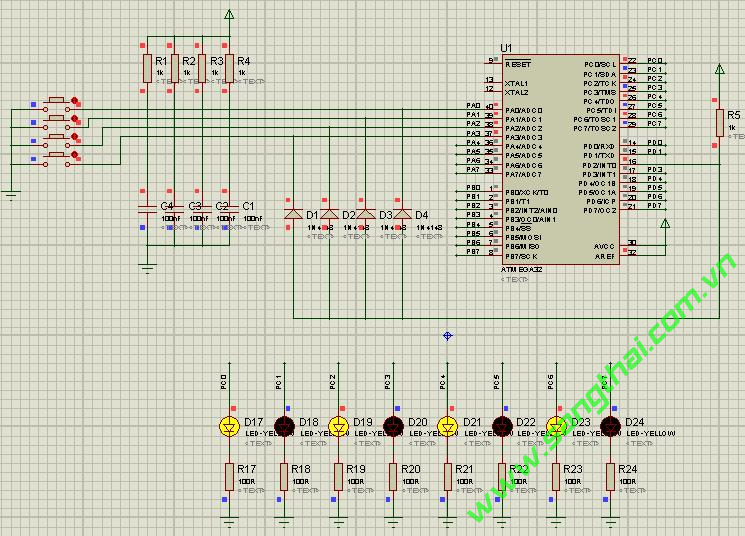
7.INT_8Leds_1Button.
- Sơ đồ mạch điện:
Sơ đồ mạch điện.
- Chương trình mẫu:
Chip type : ATmega32
Program type : Application
Clock frequency : 7.372800 MHz
Memory model : Small
External SRAM size : 0
Data Stack size : 512
************************************************** ***/#include "mega32.h"// User's define
#define LED PORTC
#define DELAY_VALUE 50000// Global variables
unsigned char counter;// External Interrupt 0 service routine
interrupt [EXT_INT0] void ext_int0_isr(void)
{
counter = (counter >= 3) ? 0 : (counter + 1);
}void my_delay(unsigned long int delay_value, unsigned char compare)
{
while ((counter == compare) && (delay_value--));
}// Declare your global variables herevoid main(void)
{
// Declare your local variables here// Input/Output Ports initialization
// Port A initialization
// Func7=In Func6=In Func5=In Func4=In Func3=In Func2=In Func1=In Func0=In
// State7=T State6=T State5=T State4=T State3=T State2=T State1=T State0=T
PORTA=0x00;
DDRA=0x00;// Port B initialization
// Func7=In Func6=In Func5=In Func4=In Func3=In Func2=In Func1=In Func0=In
// State7=T State6=T State5=T State4=T State3=T State2=T State1=T State0=T
PORTB=0x00;
DDRB=0x00;// Port C initialization
// Func7=Out Func6=Out Func5=Out Func4=Out Func3=Out Func2=Out Func1=Out Func0=Out
// State7=0 State6=0 State5=0 State4=0 State3=0 State2=0 State1=0 State0=0
PORTC=0x00;
DDRC=0xFF;// Port D initialization
// Func7=In Func6=In Func5=In Func4=In Func3=In Func2=In Func1=In Func0=In
// State7=T State6=T State5=T State4=T State3=T State2=T State1=T State0=T
PORTD=0x00;
DDRD=0x00;// Timer/Counter 0 initialization
// Clock source: System Clock
// Clock value: Timer 0 Stopped
// Mode: Normal top=FFh
// OC0 output: Disconnected
TCCR0=0x00;
TCNT0=0x00;
OCR0=0x00;// Timer/Counter 1 initialization
// Clock source: System Clock
// Clock value: Timer 1 Stopped
// Mode: Normal top=FFFFh
// OC1A output: Discon.
// OC1B output: Discon.
// Noise Canceler: Off
// Input Capture on Falling Edge
// Timer 1 Overflow Interrupt: Off
// Input Capture Interrupt: Off
// Compare A Match Interrupt: Off
// Compare B Match Interrupt: Off
TCCR1A=0x00;
TCCR1B=0x00;
TCNT1H=0x00;
TCNT1L=0x00;
ICR1H=0x00;
ICR1L=0x00;
OCR1AH=0x00;
OCR1AL=0x00;
OCR1BH=0x00;
OCR1BL=0x00;// Timer/Counter 2 initialization
// Clock source: System Clock
// Clock value: Timer 2 Stopped
// Mode: Normal top=FFh
// OC2 output: Disconnected
ASSR=0x00;
TCCR2=0x00;
TCNT2=0x00;
OCR2=0x00;// External Interrupt(s) initialization
// INT0: On
// INT0 Mode: Rising Edge
// INT1: Off
// INT2: Off
GICR|=0x40;
MCUCR=0x03;
MCUCSR=0x00;
GIFR=0x40;// Timer(s)/Counter(s) Interrupt(s) initialization
TIMSK=0x00;// Analog Comparator initialization
// Analog Comparator: Off
// Analog Comparator Input Capture by Timer/Counter 1: Off
ACSR=0x80;
SFIOR=0x00;// Global enable interrupts
#asm("sei")counter = 3;while (1)
{
switch (counter)
{
case 0:
while(1){
LED = 0xFF;
my_delay(DELAY_VALUE, 0);
if (counter != 0) break;
LED = 0x00;
my_delay(DELAY_VALUE, 0);
if (counter != 0) break;
}
break;
case 1:
while(1){
LED = 0b10101010;
my_delay(DELAY_VALUE, 1);
if (counter != 1) break;
LED = 0b01010101;
my_delay(DELAY_VALUE, 1);
if (counter != 1) break;
}
break;
case 2:
LED = 0xFF;
while(1){
if (LED == 0){
LED = 0xFF;
my_delay(DELAY_VALUE, 2);
}
if (counter != 2) break;
LED = (LED << 1)& 0b11111110;
my_delay(DELAY_VALUE, 2);
if (counter != 2) break;
}
break;
case 3:
LED = 0x00;
while(1){
if (counter != 3) break;
}
break;
default:
break;
}
};
}8.INT_8Leds_4Buttons.
- Sơ đồ mạch điện:
Sơ đồ mạch điện.
- Chương trình mẫu:
Chip type : ATmega32
Program type : Application
Clock frequency : 7.372800 MHz
Memory model : Small
External SRAM size : 0
Data Stack size : 512
************************************************** ***/#include "mega32.h"// User's define
#define LED PORTC
#define DELAY_VALUE 50000
// Global variables
unsigned char pin_state = 0;// External Interrupt 0 service routine
interrupt [EXT_INT0] void ext_int0_isr(void)
{
if (PINA.0==0) pin_state = 0;
if (PINA.1==0) pin_state = 1;
if (PINA.2==0) pin_state = 2;
if (PINA.3==0) pin_state = 3;
}void my_delay(unsigned long int delay_value, unsigned char state)
{
while ((pin_state == state) && (delay_value--));
}// Declare your global variables herevoid main(void)
{
// Declare your local variables here
//unsigned char temp;
// Input/Output Ports initialization
// Port A initialization
// Func7=In Func6=In Func5=In Func4=In Func3=In Func2=In Func1=In Func0=In
// State7=T State6=T State5=T State4=T State3=T State2=T State1=T State0=T
PORTA=0x00;
DDRA=0x00;// Port B initialization
// Func7=In Func6=In Func5=In Func4=In Func3=In Func2=In Func1=In Func0=In
// State7=T State6=T State5=T State4=T State3=T State2=T State1=T State0=T
PORTB=0x00;
DDRB=0x00;// Port C initialization
// Func7=Out Func6=Out Func5=Out Func4=Out Func3=Out Func2=Out Func1=Out Func0=Out
// State7=0 State6=0 State5=0 State4=0 State3=0 State2=0 State1=0 State0=0
PORTC=0x00;
DDRC=0xFF;// Port D initialization
// Func7=In Func6=In Func5=In Func4=In Func3=In Func2=In Func1=In Func0=In
// State7=T State6=T State5=T State4=T State3=T State2=T State1=T State0=T
PORTD=0x00;
DDRD=0x00;// Timer/Counter 0 initialization
// Clock source: System Clock
// Clock value: Timer 0 Stopped
// Mode: Normal top=FFh
// OC0 output: Disconnected
TCCR0=0x00;
TCNT0=0x00;
OCR0=0x00;// Timer/Counter 1 initialization
// Clock source: System Clock
// Clock value: Timer 1 Stopped
// Mode: Normal top=FFFFh
// OC1A output: Discon.
// OC1B output: Discon.
// Noise Canceler: Off
// Input Capture on Falling Edge
// Timer 1 Overflow Interrupt: Off
// Input Capture Interrupt: Off
// Compare A Match Interrupt: Off
// Compare B Match Interrupt: Off
TCCR1A=0x00;
TCCR1B=0x00;
TCNT1H=0x00;
TCNT1L=0x00;
ICR1H=0x00;
ICR1L=0x00;
OCR1AH=0x00;
OCR1AL=0x00;
OCR1BH=0x00;
OCR1BL=0x00;// Timer/Counter 2 initialization
// Clock source: System Clock
// Clock value: Timer 2 Stopped
// Mode: Normal top=FFh
// OC2 output: Disconnected
ASSR=0x00;
TCCR2=0x00;
TCNT2=0x00;
OCR2=0x00;// External Interrupt(s) initialization
// INT0: On
// INT0 Mode: Falling Edge
// INT1: Off
// INT2: Off
GICR|=0x40;
MCUCR=0x02;
MCUCSR=0x00;
GIFR=0x40;// Timer(s)/Counter(s) Interrupt(s) initialization
TIMSK=0x00;// Analog Comparator initialization
// Analog Comparator: Off
// Analog Comparator Input Capture by Timer/Counter 1: Off
ACSR=0x80;
SFIOR=0x00;// Global enable interrupts
#asm("sei")pin_state = 3;while (1)
{
switch (pin_state)
{
case 0:
while(1){
LED = 0xFF;
my_delay(DELAY_VALUE, 0);
if (pin_state != 0) break;
LED = 0x00;
my_delay(DELAY_VALUE, 0);
if (pin_state != 0) break;
}
break;
case 1:
while(1){
LED = 0b10101010;
my_delay(DELAY_VALUE, 1);
if (pin_state != 1) break;
LED = 0b01010101;
my_delay(DELAY_VALUE, 1);
if (pin_state != 1) break;
}
break;
case 2:
LED = 0xFF;
while(1){
if (LED == 0){
LED = 0xFF;
my_delay(DELAY_VALUE, 2);
}
if (pin_state != 2) break;
LED = (LED << 1)& 0b11111110;
my_delay(DELAY_VALUE, 2);
if (pin_state != 2) break;
}
break;
case 3:
LED = 0x00;
while(1){
if (pin_state != 3) break;
}
break;
default:
break;
}
};
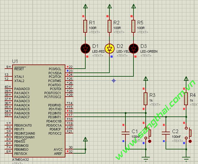
}9.INT_Nested.
- Sơ đồ mạch điện:
Sơ đồ mạch điện.
- Chương trình mẫu:
Chip type : ATmega32
Program type : Application
Clock frequency : 7.372800 MHz
Memory model : Small
External SRAM size : 0
Data Stack size : 512
************************************************** ***/#include "mega32.h"
#include "delay.h"#define LED1 PORTC.0
#define LED2 PORTC.1
#define LED PORTC.2#define ON 0
#define OFF 1// External Interrupt 0 service routine
interrupt [EXT_INT0] void ext_int0_isr(void)
{
unsigned char i;
#asm("sei")
for (i = 0; i < 8; i++){
LED1 = ON;
delay_ms(500);
LED1 = OFF;
delay_ms(500);
}
#asm("cli")
}// External Interrupt 1 service routine
interrupt [EXT_INT1] void ext_int1_isr(void)
{
unsigned char i;
#asm("sei")
for (i = 0; i < 8; i++){
LED2 = ON;
delay_ms(500);
LED2 = OFF;
delay_ms(500);
}
#asm("cli")
}// Declare your global variables herevoid main(void)
{
// Declare your local variables here// Input/Output Ports initialization
// Port A initialization
// Func7=In Func6=In Func5=In Func4=In Func3=In Func2=In Func1=In Func0=In
// State7=T State6=T State5=T State4=T State3=T State2=T State1=T State0=T
PORTA=0x00;
DDRA=0x00;// Port B initialization
// Func7=In Func6=In Func5=In Func4=In Func3=In Func2=In Func1=In Func0=In
// State7=T State6=T State5=T State4=T State3=T State2=T State1=T State0=T
PORTB=0x00;
DDRB=0x00;// Port C initialization
// Func7=In Func6=In Func5=In Func4=In Func3=In Func2=In Func1=Out Func0=Out
// State7=T State6=T State5=T State4=T State3=T State2=T State1=1 State0=1
PORTC=0x07;
DDRC=0x07;// Port D initialization
// Func7=In Func6=In Func5=In Func4=In Func3=In Func2=In Func1=In Func0=In
// State7=T State6=T State5=T State4=T State3=T State2=T State1=T State0=T
PORTD=0x00;
DDRD=0x00;// Timer/Counter 0 initialization
// Clock source: System Clock
// Clock value: Timer 0 Stopped
// Mode: Normal top=FFh
// OC0 output: Disconnected
TCCR0=0x00;
TCNT0=0x00;
OCR0=0x00;// Timer/Counter 1 initialization
// Clock source: System Clock
// Clock value: Timer 1 Stopped
// Mode: Normal top=FFFFh
// OC1A output: Discon.
// OC1B output: Discon.
// Noise Canceler: Off
// Input Capture on Falling Edge
// Timer 1 Overflow Interrupt: Off
// Input Capture Interrupt: Off
// Compare A Match Interrupt: Off
// Compare B Match Interrupt: Off
TCCR1A=0x00;
TCCR1B=0x00;
TCNT1H=0x00;
TCNT1L=0x00;
ICR1H=0x00;
ICR1L=0x00;
OCR1AH=0x00;
OCR1AL=0x00;
OCR1BH=0x00;
OCR1BL=0x00;// Timer/Counter 2 initialization
// Clock source: System Clock
// Clock value: Timer 2 Stopped
// Mode: Normal top=FFh
// OC2 output: Disconnected
ASSR=0x00;
TCCR2=0x00;
TCNT2=0x00;
OCR2=0x00;// External Interrupt(s) initialization
// INT0: On
// INT0 Mode: Falling Edge
// INT1: On
// INT1 Mode: Falling Edge
// INT2: Off
GICR|=0xC0;
MCUCR=0x0A;
MCUCSR=0x00;
GIFR=0xC0;// Timer(s)/Counter(s) Interrupt(s) initialization
TIMSK=0x00;// Analog Comparator initialization
// Analog Comparator: Off
// Analog Comparator Input Capture by Timer/Counter 1: Off
ACSR=0x80;
SFIOR=0x00;// Global enable interrupts
#asm("sei")while (1)
{
LED = ON;
delay_ms(100);
LED = OFF;
delay_ms(100);
};
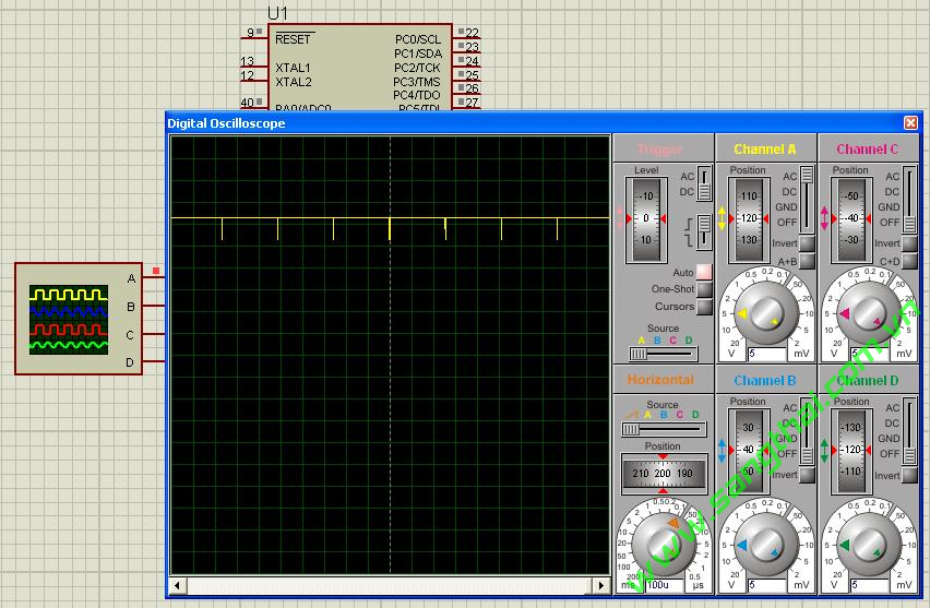
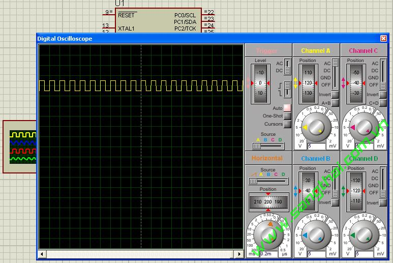
}10.TIMER0_Fast_PWM.
- Sơ đồ mạch điện:
Sơ đồ mạch điện.
- Chương trình mẫu:
Chip type : ATmega32
Program type : Application
Clock frequency : 8.000000 MHz
Memory model : Small
External SRAM size : 0
Data Stack size : 512
************************************************** ***/#include "mega32.h"
#include "delay.h"// Declare your global variables herevoid main(void)
{
// Declare your local variables here// Input/Output Ports initialization
// Port A initialization
// Func7=In Func6=In Func5=In Func4=In Func3=In Func2=In Func1=In Func0=In
// State7=T State6=T State5=T State4=T State3=T State2=T State1=T State0=T
PORTA=0x00;
DDRA=0x00;// Port B initialization
// Func7=In Func6=In Func5=In Func4=In Func3=Out Func2=In Func1=In Func0=In
// State7=T State6=T State5=T State4=T State3=0 State2=T State1=T State0=T
PORTB=0x00;
DDRB=0x08;// Port C initialization
// Func7=In Func6=In Func5=In Func4=In Func3=In Func2=In Func1=In Func0=In
// State7=T State6=T State5=T State4=T State3=T State2=T State1=T State0=T
PORTC=0x00;
DDRC=0x00;// Port D initialization
// Func7=In Func6=In Func5=In Func4=In Func3=In Func2=In Func1=In Func0=In
// State7=T State6=T State5=T State4=T State3=T State2=T State1=T State0=T
PORTD=0x00;
DDRD=0x00;// Timer/Counter 0 initialization
// Clock source: System Clock
// Clock value: 1000.000 kHz
// Mode: Fast PWM top=FFh
// OC0 output: Non-Inverted PWM
TCCR0=0x6A;
TCNT0=0x00;
OCR0=0x00;// Timer/Counter 1 initialization
// Clock source: System Clock
// Clock value: Timer 1 Stopped
// Mode: Normal top=FFFFh
// OC1A output: Discon.
// OC1B output: Discon.
// Noise Canceler: Off
// Input Capture on Falling Edge
// Timer 1 Overflow Interrupt: Off
// Input Capture Interrupt: Off
// Compare A Match Interrupt: Off
// Compare B Match Interrupt: Off
TCCR1A=0x00;
TCCR1B=0x00;
TCNT1H=0x00;
TCNT1L=0x00;
ICR1H=0x00;
ICR1L=0x00;
OCR1AH=0x00;
OCR1AL=0x00;
OCR1BH=0x00;
OCR1BL=0x00;// Timer/Counter 2 initialization
// Clock source: System Clock
// Clock value: Timer 2 Stopped
// Mode: Normal top=FFh
// OC2 output: Disconnected
ASSR=0x00;
TCCR2=0x00;
TCNT2=0x00;
OCR2=0x00;// External Interrupt(s) initialization
// INT0: Off
// INT1: Off
// INT2: Off
MCUCR=0x00;
MCUCSR=0x00;// Timer(s)/Counter(s) Interrupt(s) initialization
TIMSK=0x00;// Analog Comparator initialization
// Analog Comparator: Off
// Analog Comparator Input Capture by Timer/Counter 1: Off
ACSR=0x80;
SFIOR=0x00;while (1)
{
// OCR can be set from 0 to 255
OCR0 = 255; // 100%
delay_ms(1000);
OCR0 = 150; // 58.8%
delay_ms(1000);
OCR0 = 50; // 19.6%
delay_ms(1000);
OCR0 = 0; // 0%
delay_ms(1000);
};
}11.TIMER0_Output_Comp.
- Sơ đồ mạch điện:
Sơ đồ mạch điện.
- Chương trình mẫu:
Chip type : ATmega32
Program type : Application
Clock frequency : 8.000000 MHz
Memory model : Small
External SRAM size : 0
Data Stack size : 512
************************************************** ***/#include "mega32.h"// Declare your global variables herevoid main(void)
{
// Declare your local variables here// Input/Output Ports initialization
// Port A initialization
// Func7=In Func6=In Func5=In Func4=In Func3=In Func2=In Func1=In Func0=In
// State7=T State6=T State5=T State4=T State3=T State2=T State1=T State0=T
PORTA=0x00;
DDRA=0x00;// Port B initialization
// Func7=In Func6=In Func5=In Func4=In Func3=Out Func2=In Func1=In Func0=In
// State7=T State6=T State5=T State4=T State3=0 State2=T State1=T State0=T
PORTB=0x00;
DDRB=0x08;// Port C initialization
// Func7=In Func6=In Func5=In Func4=In Func3=In Func2=In Func1=In Func0=In
// State7=T State6=T State5=T State4=T State3=T State2=T State1=T State0=T
PORTC=0x00;
DDRC=0x00;// Port D initialization
// Func7=In Func6=In Func5=In Func4=In Func3=In Func2=In Func1=In Func0=In
// State7=T State6=T State5=T State4=T State3=T State2=T State1=T State0=T
PORTD=0x00;
DDRD=0x00;// Timer/Counter 0 initialization
// Clock source: System Clock
// Clock value: 1000.000 kHz
// Mode: CTC top=OCR0
// OC0 output: Toggle on compare match
TCCR0=0x1A;
TCNT0=0x00;
OCR0=0x63;// Timer/Counter 1 initialization
// Clock source: System Clock
// Clock value: Timer 1 Stopped
// Mode: Normal top=FFFFh
// OC1A output: Discon.
// OC1B output: Discon.
// Noise Canceler: Off
// Input Capture on Falling Edge
// Timer 1 Overflow Interrupt: Off
// Input Capture Interrupt: Off
// Compare A Match Interrupt: Off
// Compare B Match Interrupt: Off
TCCR1A=0x00;
TCCR1B=0x00;
TCNT1H=0x00;
TCNT1L=0x00;
ICR1H=0x00;
ICR1L=0x00;
OCR1AH=0x00;
OCR1AL=0x00;
OCR1BH=0x00;
OCR1BL=0x00;// Timer/Counter 2 initialization
// Clock source: System Clock
// Clock value: Timer 2 Stopped
// Mode: Normal top=FFh
// OC2 output: Disconnected
ASSR=0x00;
TCCR2=0x00;
TCNT2=0x00;
OCR2=0x00;// External Interrupt(s) initialization
// INT0: Off
// INT1: Off
// INT2: Off
MCUCR=0x00;
MCUCSR=0x00;// Timer(s)/Counter(s) Interrupt(s) initialization
TIMSK=0x00;// Analog Comparator initialization
// Analog Comparator: Off
// Analog Comparator Input Capture by Timer/Counter 1: Off
ACSR=0x80;
SFIOR=0x00;while (1)
{
// Place your code here };
}12.TIMER0_OVF_Int.
- Sơ đồ mạch điện:
Sơ đồ mạch điện.
- Chương trình mẫu:
Chip type : ATmega32
Program type : Application
Clock frequency : 8.000000 MHz
Memory model : Small
External SRAM size : 0
Data Stack size : 512
************************************************** ***/#include "mega32.h"#define LED PORTC.0// Global variables
unsigned int count = 0;// Timer 0 overflow interrupt service routine
interrupt [TIM0_OVF] void timer0_ovf_isr(void)
{
TCNT0 = 6;
if (count++ == 2000){
count = 0;
LED = ~LED;
}
}// Declare your global variables herevoid main(void)
{
// Declare your local variables here// Input/Output Ports initialization
// Port A initialization
// Func7=In Func6=In Func5=In Func4=In Func3=In Func2=In Func1=In Func0=In
// State7=T State6=T State5=T State4=T State3=T State2=T State1=T State0=T
PORTA=0x00;
DDRA=0x00;// Port B initialization
// Func7=In Func6=In Func5=In Func4=In Func3=In Func2=In Func1=In Func0=In
// State7=T State6=T State5=T State4=T State3=T State2=T State1=T State0=T
PORTB=0x00;
DDRB=0x00;// Port C initialization
// Func7=In Func6=In Func5=In Func4=In Func3=In Func2=In Func1=In Func0=Out
// State7=T State6=T State5=T State4=T State3=T State2=T State1=T State0=1
PORTC=0x01;
DDRC=0x01;// Port D initialization
// Func7=In Func6=In Func5=In Func4=In Func3=In Func2=In Func1=In Func0=In
// State7=T State6=T State5=T State4=T State3=T State2=T State1=T State0=T
PORTD=0x00;
DDRD=0x00;// Timer/Counter 0 initialization
// Clock source: System Clock
// Clock value: 1000.000 kHz
// Mode: Normal top=FFh
// OC0 output: Disconnected
TCCR0=0x02;
TCNT0=0x06;
OCR0=0x00;// Timer/Counter 1 initialization
// Clock source: System Clock
// Clock value: Timer 1 Stopped
// Mode: Normal top=FFFFh
// OC1A output: Discon.
// OC1B output: Discon.
// Noise Canceler: Off
// Input Capture on Falling Edge
// Timer 1 Overflow Interrupt: Off
// Input Capture Interrupt: Off
// Compare A Match Interrupt: Off
// Compare B Match Interrupt: Off
TCCR1A=0x00;
TCCR1B=0x00;
TCNT1H=0x00;
TCNT1L=0x00;
ICR1H=0x00;
ICR1L=0x00;
OCR1AH=0x00;
OCR1AL=0x00;
OCR1BH=0x00;
OCR1BL=0x00;// Timer/Counter 2 initialization
// Clock source: System Clock
// Clock value: Timer 2 Stopped
// Mode: Normal top=FFh
// OC2 output: Disconnected
ASSR=0x00;
TCCR2=0x00;
TCNT2=0x00;
OCR2=0x00;// External Interrupt(s) initialization
// INT0: Off
// INT1: Off
// INT2: Off
MCUCR=0x00;
MCUCSR=0x00;// Timer(s)/Counter(s) Interrupt(s) initialization
TIMSK=0x01;// Analog Comparator initialization
// Analog Comparator: Off
// Analog Comparator Input Capture by Timer/Counter 1: Off
ACSR=0x80;
SFIOR=0x00;// Global enable interrupts
#asm("sei")while (1)
{
// Place your code here };


http://dientu686.com/
Không có nhận xét nào:
Đăng nhận xét